I'm really continuing discussion on a previous question posed 2 years ago ("Identifying a toner chip and its communication protocol to re-program it").
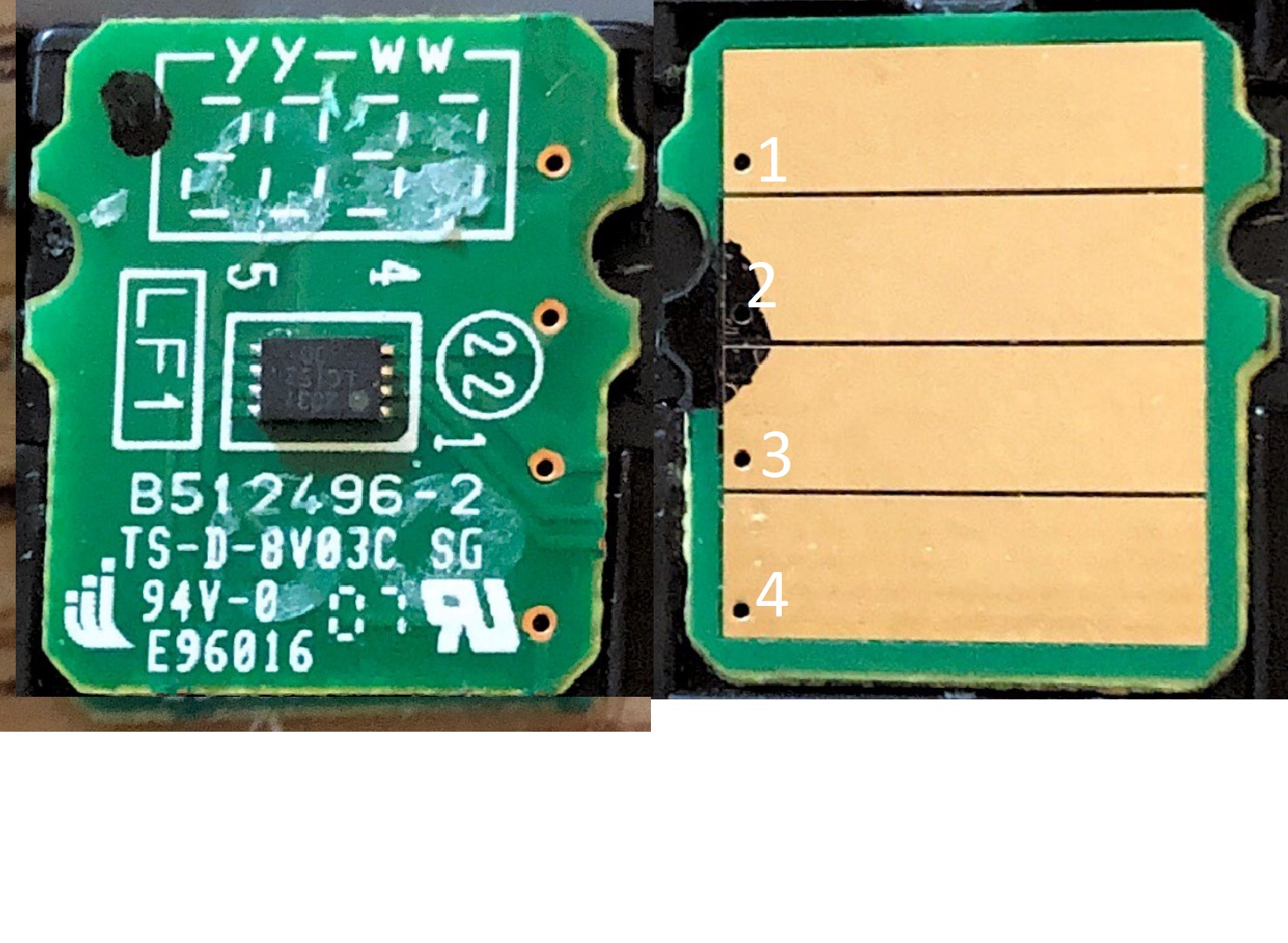
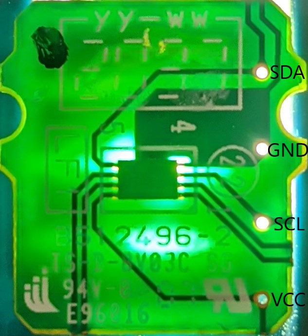
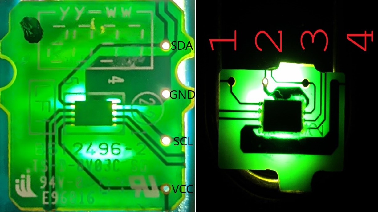
I found that user to have the most information (which overall isn't a lot but more useful than anything on the Internet and nothing more has been posted since then! As of December 2021). For mine the context is for Brother DCP-L2550DW for toner TN-760 or TN-730. Rather than TN227 or TN223. I followed the same format and made similar assumptions. Based on their discovery, I sort of just put my hypotheses here for SDA, GND, SCL, VCC (literally what the previous discussion Answer #1 stated as their guesswork and for whom 1 responder said it was correct for them?). I'm no engineer, so I had to just make analogous assumptions. For communication’s sake I put 1, 2, 3, and 4 for Pad 1, Pad 2, Pad 3, and Pad 4.
I'm using IC2 Scanner program and running it in Arduino using ELEGOO UNO R3. The problem is that when I physically connect to the configuration and any combination thereof and run the code (or “serial monitor”) the output stops. While I'm still physically holding the pins to the “pads” on the microchip (i.e. the FOUR fat rectangular contacts) the code is at a blank or just “writing”. Upon release of the pins, it spews out gibberish, which I assume is the tested address for IC2. I know I'm doing something wrong.
My assumption based on the previous forum is that GROUND is 2 and VCC is 4. I have mixed all other combos to no avail. I strongly feel there is a noob mistake I'm doing.
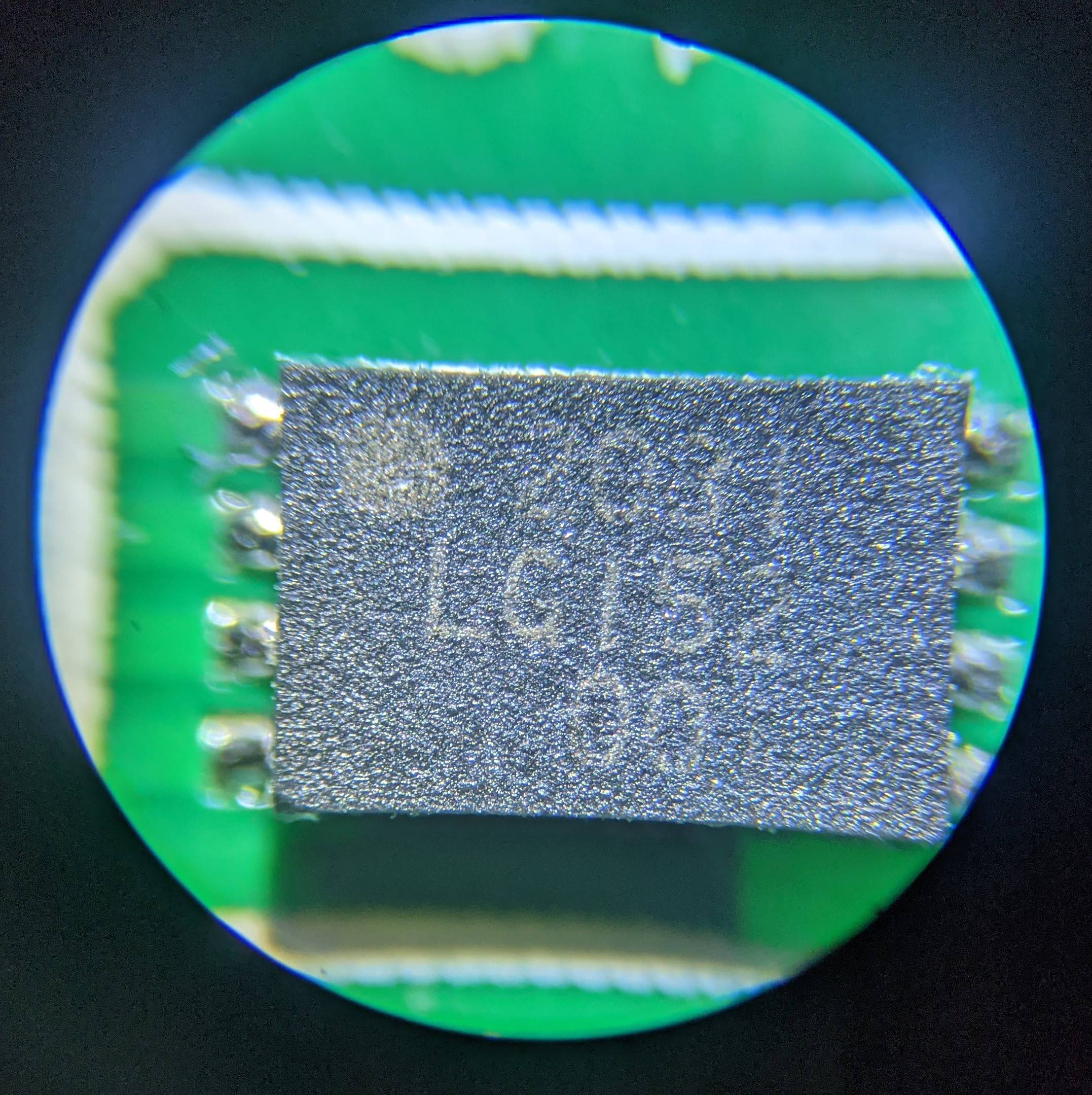
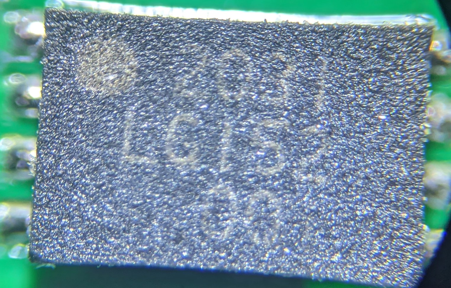
Want it thrown out there that I cannot identify the manufacturer for Brother and I agree with the previous user that whoever they partnered with encrypted their identity on the chip. I went on a few websites to identify WHO it is but I do not see any entity with a reverse “RJ” with “iii” symbol. I cannot find locate the data sheet to explain the bus controller configuration and what is SCL, SDA, GND, or VCC.
So my option is simply reverse engineer with “IC2 Scanner” with arduino OR “logical analyzer”. I'm opting for the former. I figured out how to bypass the printer “low toner” message and can print. But I am dead curious how to reset this toner microchip, as I don't like this man-made block for DIYers for refilling our own cartridge. The chips can be reset bc I noticed on the market for Amazon or eBay some third party are selling these chips with similar design (New Era Toner). This microchip (IC2 + EEPROM or EPROM) has a similar look, with the “M” and inverted “M” or “W” on opposite top or sides of the microchip (see picture). And from those selling from 3rd party, It's consistent in design. The design is also similar to the card posted on this forum 2 years ago, albeit some differences. So it's gotta be some mass batch for brother printers and a partner for whose identification remains elusive. I feel like their identity is within reach. Here is a website that I used but did not have my answer: How to identify integrated circuit (chip) manufacturers by their logos/P-T.
I am not averse to buying the genuine parts but based on some articles (What You Need To Know About Brother Microchip Cartridges). Brother is now aggressive and jacking up the price to HALF the cost of the printer, which I find revolting. And they are doing it BC they found a way to hijack our printers with the microchip. I figured I would buy another microchip third party maybe after 4-5 refills on my own (which BTW this printer is relatively new model 2021 so I discovered a chip on it). But even those have issues with low count or compatibility.
Anyways thanks for your help. Not an engineer but I have rudimentary understanding of hardware software. I know fundamentals of programming or enough of it. My previous experience was successfuly resetting toner cartridge for Ricoh printers but finding Brother to be rather annoying in lack of information. Reverse engineering seems to be the only key to get this to work and a few ppl figured out their way (3rd party sellers).
PS - "Continue" mode that allows us to print after "low toner" status is still within the parameters of what Brother wants. It will disable your printer after using it once. So I do not have a means of printing further with this chip. What is Toner Continue Mode? Brother.
Update: I have resigned to finding manufacturer. But I wanted to make one last point. Here is image of the previous forum (linked on top) side-by-side with my picture. One of the hidden commenters (5th responder) below on that discussion confirmed they were successful based on the hypothesus of the first commenter. And if that is true I noticed similarity in design as far as the circuitry on mine and the other original poster. And if THAT is true and the supposed circuitry is correct then possibly I have more of a software issue on the I2C scanner software. And I also don't know if mine is 5 volts or 3.3 volts (but I really want to say it would be 3.3 volts bc of my unscientific hunch). I would have to invest in a "logic analyzer" which is where I might suspend activity for now since that is another rabbit hole. I added a link to a DIY Youtuber who is also not a professional engineer but who did a fantastic job explaining what he knew. In the comment section (gotta dig a little deep but not too longer) there is a reference for the I2C scan code to READ the chip. Under his guidance it supposedly is able to scan for the address but that's assuming one knows the circuitry of the EEPROM. Without knowing that step its just plain hard to continue. I included it to show what code I was using for my arduino UNO R3 which is producing the same results with the proposed configuration as when I don't touch the wires to anything (i.e. serial output runs address gibberish when I touch nothing on the other end).
Side by side comparison of the two EEPROMS, original of which had confirmation of successful result. I had no luck.
YouTube EEPROM Explanation with Source Code in comment section
