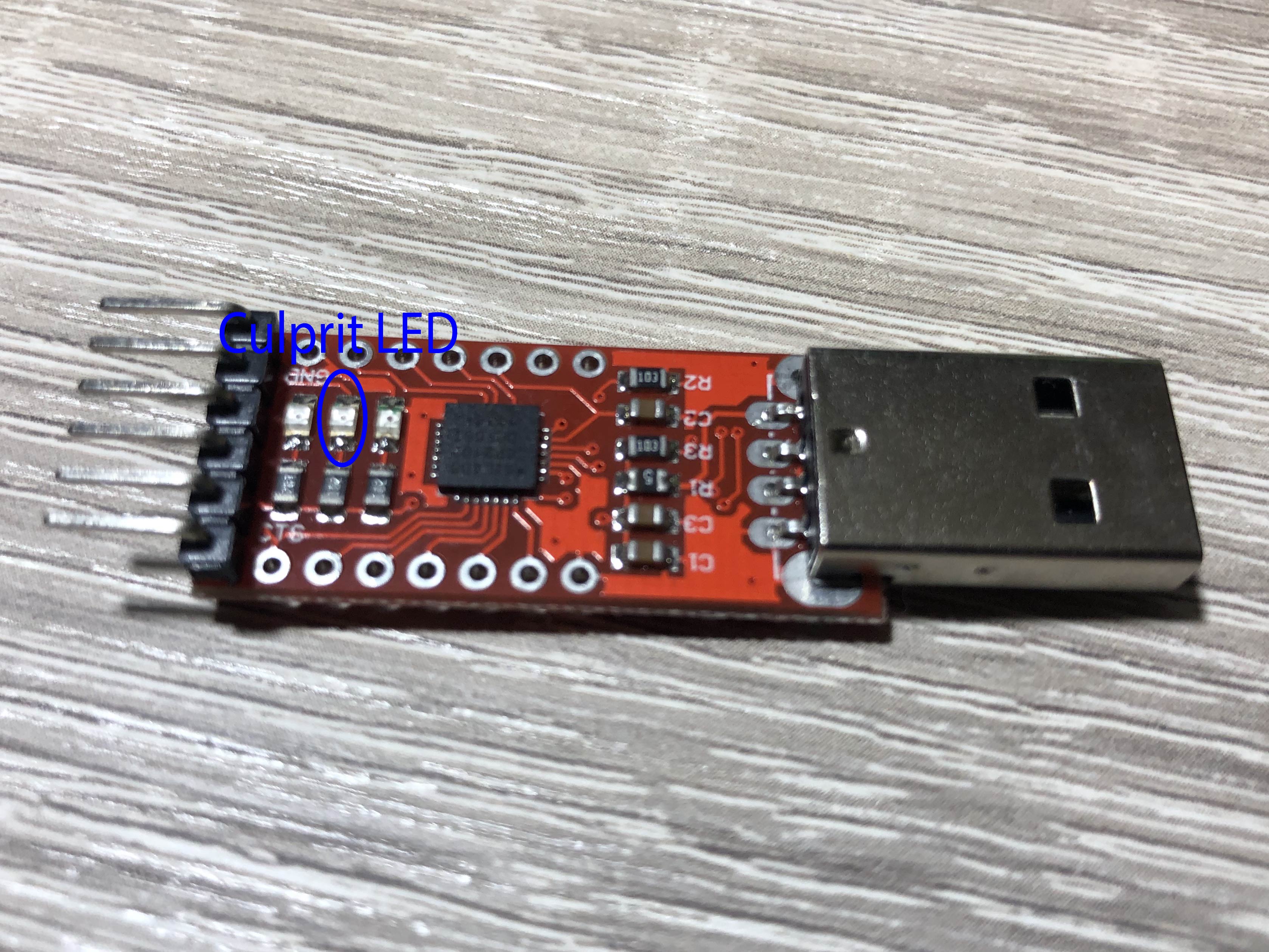
I have a modem that I'm trying to get into. It's composed of two SoCs, both with UART headers. I was already successful trying to connect to the first SoC's UART, with my USB-to-UART CP2102 decoder chip happily both sending and receiving bytes at 115200bps 8N1, being dropped at a Busybox shell.
I hadn't had the same luck with the second SoC. It has the exact same physical header, and judging by the signal on the oscilloscope it seems to be the same kind of UART as the first one, that I can even decode some bytes manually, but the CP2102 seems unable to.
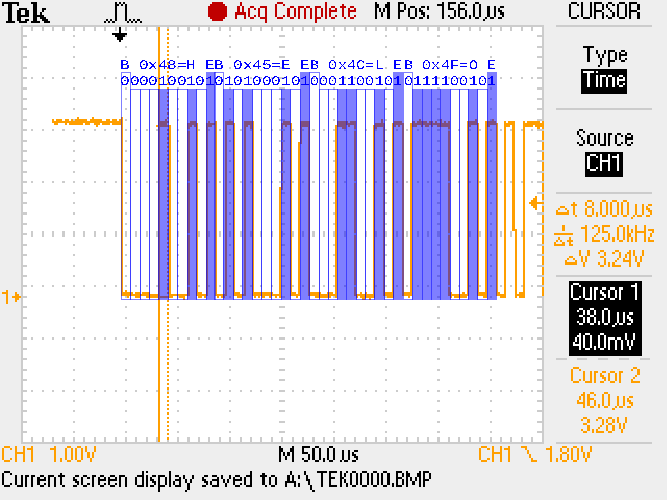
Here you can see the first four bytes sent on the TX line immediately when the board is powered on with a manual decoding, inferring that the signal is indeed UART with 0-3.3V levels, 115200bps (8.0 microseconds per bit), one stop bit and no parity bits:
If my assumptions are right, the first four bytes are an ASCII "HELO". Superimposed on the image there's my manual decoding. B is the Start Bit, E is the Stop Bit, and I'm assuming the least significant bit comes first.
Some variations on the encoding settings have already been tried, like setting odd and even parity, using one or two stop bits, and even using a speed immediately above or below. The terminal, however, still shows nothing. I know that the decoder is working because it's happily receiving data when connected to the first SoC, but it does not decode anything from the second.
I disabled both hardware flow control lines and software flow control signals on the decoder, and I'm failing to see anything else that might be wrong, except some minor timing issues: the baud seems to have 8.6~8 microseconds instead of 8.0. However, I think that's still within the error margin.
The SoC in question is a Broadcom BCM68380, which someone already posted the bootlog on the internet and indeed it shows the same first four bytes: https://www.tripleoxygen.net/wiki/modem/rtf3505vw-gv
What could I be missing here? Why can't I decode this?

