7

I'm trying to reverse engineer a 2Wire ADSL modem/router, mainly for practice. I opened it and found a serial port (with a header conveniently already in place) but I'm not getting any useful data out of it, only gibberish. The device does work (well enough to present its web UI), only this port is giving me trouble.

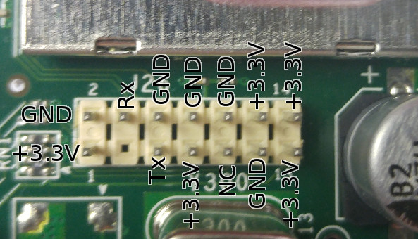
Deciphered pinout

Why I'm pretty sure this is the right pinout:

  • No other pins/pads anywhere on the board output anything that looks like data
  • If I short Tx and Rx, or connect to my terminal and spam spacebar, it fails to boot up (LED stays red)
  • The one NC pin looks the same on the oscilliscope as when it's not connected (slight noise instead of a steady 0V or 3V)

What I've tried:

  • Several baud rates: 1200, 1800, 2400, 4800, 9600, 19200, 38400, 57600, 115200, 230400, 460800, 500000, 921600, 960000
  • Various combinations of parity and stop-bit settings
  • Connecting it to a USB FTDI adapter
  • Connecting it to the serial pins of a Raspberry Pi
  • Adding pullup and pulldown resistors to Tx
  • Inverting the Tx signal in hardware and in software
  • Leaving the serial ground unconnected

No matter what, the data that comes in is gibberish, or nothing at all.

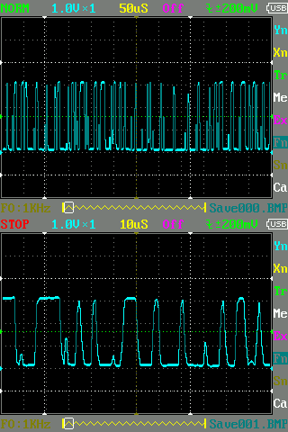
On my scope it definitely looks like data, jumping around between 0V and +3.3V for ~1/4 second at power on, then going to +3.3V and staying there.

Signal analysis

But I just can't seem to find any combination of settings and connections that give me any coherent output. Am I missing something?

(For the record, I do own this modem.)
4
  • The fact that it's a 14-pin header means it may be a common JTAG interface. What's the model number of the router? Commented Apr 25, 2016 at 12:31
  • Model is 2Wire 2701HG-H.
    – Rena
    Commented Apr 25, 2016 at 21:21
  • Here's a post about a very similar router: link. It looks like the lines you've labelled as Rx and Tx are two of the I2C lines. Several of the pins are also used for JTAG, which may allow for you to get at the internals of the thing, but I'm going to venture a guess that it's pretty locked down. Commented Apr 26, 2016 at 12:56
  • You're right. I traced those pins back to the serial EEPROM nearby. Not sure how I missed the clock signal there. Can you post that as an answer so I can accept it?
    – Rena
    Commented Apr 27, 2016 at 16:09

2 Answers 2

4

If this is data, then there should be a common clock, with the raising/falling edge signals all on individual ticks of that clock.

I scaled the bottom half of your scope output by 500% horizontally, and had gimp overlay a grid on it, playing with the width and shift of the grid until i found something that looks like it could be the clock (click the image to see it in full scale):

enter image description here

So yes, this is probably serial data. And, if i understand the "10 us" display correctly, your white grid dotted lines are 10 us apart, which means my grid lines are 1.6 us apart, which means the bit rate should be somewhere around 1/0.0000016=625000 baud, which is different enough from your bit rates to prevent them from working. If you can, try setting the bit rate to something closer to that.

Still, i see trouble with that signal even if you use the correct bit rate. The slopes of the raising and falling edges of your signal are, in some cases, way too flat - see the green markers. And there are spikes that look like line noise (red markers). To my eye, this looks like there's too much capacitance on that data line. This could explain the flat slopes - the serial driver isn't able to put out enough current to raise the signal against the capacitance - and it could explain the red markers as well - a short pulse on TX doesn't even manage to raise the voltage to the value it should.

But, i'm a bit out of my depth here. Maybe the friendly people at the EE stack exchange can be a bit more helpful fixing this.

1
  • there is also another reason possible. Some devices do not use DC/DC converters for RS232 voltage conversion like MAX232 instead the power is obtained directly from RX (TX from the host device) so if a bigger gap in receiving signal is present the voltage drops ... and first few bits are distorted.
    – Spektre
    Commented Jun 8, 2016 at 11:40
3

Your signal is very degraded: your rise and fall times are too slow relative to the bit rate. If the signal really looks as your scope plot shows, and this is not just a measurement issue, then it's no surprise that you cannot get coherent data out of it. Serial port signals should have very clean and well-defined rise and fall times relative to the baud rate.

To begin with, try getting the cleanest possible scope trace. Zoom in more - at the horizontal timebase that you're using, with those messy pulses, getting a good idea of what's going on is difficult. Then, make sure you're using your scope's 10x mode on the probe, and that any loading features (e.g. 75Ω termination) are off. Make sure your probe's ground is solid, and that there is nothing else on the TX line other than your scope. Then, measure again. What scope are you using?

Assuming this is a standard asynchronous serial signal, there should be a high-to-low transition marking the start of every byte (the start bit). For continuous transmissions, these should be spaced out evenly. Looking at your top plot, it looks like this might be the case, but I'm having a hard time aligning a grid like that to your bottom plot. Try to improve your signal quality as much as possible, then zoom in to a sparse (mostly-zero) section of the capture and see if you can confirm a pattern like that. If this is ASCII, you should be able to find some space characters, which are 0x20, and should be represented by the bit sequence 0000001001 (or 000000100x1 if parity is enabled, append another 1 or half of it if there are 2 or 1.5 stopbits respectively). If you can't find the evenly spaced out start bit transitions, then this probably isn't a standard UART output.

Either way, things should be a lot clearer once you solve your signal integrity issues.

Edit: also make sure your scope probe is properly compensated!

Your Answer

By clicking “Post Your Answer”, you agree to our terms of service and acknowledge you have read our privacy policy.

Not the answer you're looking for? Browse other questions tagged or ask your own question.