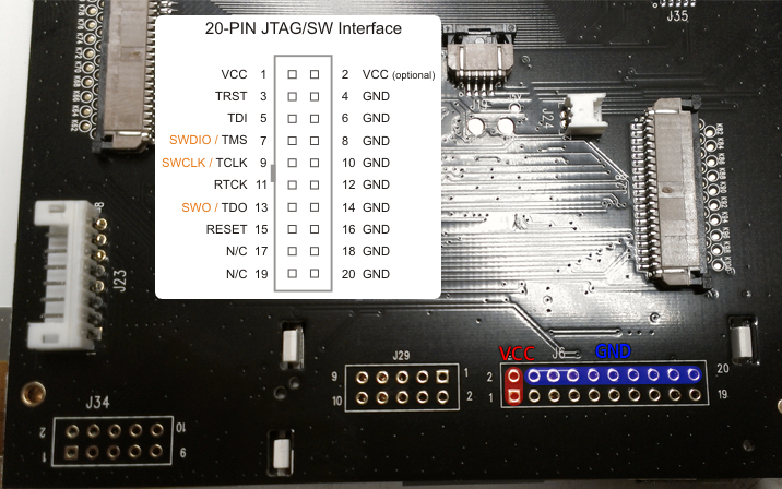
JTAG was initially created to test/verify hardware devices. The process is called boundary scanning and JTAG was named after the working group: Joint Test Action Group, some time in the 1980s.
The idea was to define an interface that could be used to test hardware (micro controllers and connected peripherals after manufacturing). I.e. after development of the hardware and subsequent production of it.
The devices used to do the boundary scan according to JTAG are called JTAG probes. They used to be connected to the parallel port of your machine, but these days are more often connected via USB and based on one of the FTDI chips.
On a PCB the chip(s) and peripherals form a "daisy chain" connected to the TAP (test access port). So you can test the various components through one port. The instruction BYPASS is used to tell a device earlier on the chain to ignore your commands and pass them on. IDCODE is used to identify the device and a few basic characteristics.
A neat overview of some technical details can be found here: JTAG - A technical overview, but the Wikipedia article and its reference list also provide valuable information. Keep in mind that this was established before the WWW came to be and that a lot of information regarding it has been banned onto dead trees.
The term boundary scan is still used to describe the process and makes up part of the acronym BSDL (boundary scan description language), which you would normally get in touch with if you were to boundary scan a device/chip and the vendor expected you to do that. Otherwise they tend to be pretty secretive about it. The reason for the secrecy being that they essentially give away a part of their hardware design, which most of these hardware vendors consider a trade secet. I've had the luck to get access to the BSDL file, under NDA, even though it wasn't for the exact silicon revision I was debugging. But I was assured that the BSDL file would work just fine with the silicon revision of the chip I had. But unless you can afford to destroy your hardware, you have to make sure that your BSDL data matches the hardware you connect to.
These days JTAG isn't just used for testing only, though. Of course hardware-debugging is a subset of testing, so this is not what I mean. What I mean is that JTAG probes also allow you to flash firmware on otherwise defunct hardware. And that is essential in debricking bricked hardware.
Possible problems
There are several problems in using JTAG which you have to overcome aside from identifying the connectors. And I'll ignore the bit Mellowcandle mentioned in his answer.
You have to be confident that you got things right, because otherwise you can fry your hardware instead of, for example, debricking it.
Identify the JTAG pins
Often you'll find TMS, TCK, TDI and so on inscribed on your PCB, so you know you're dealing with a device that supports JTAG. Magnifying glasses may be of help ;)
But this isn't really an arcane art - it gets more difficult when the pins aren't labeled and you need to rely on third-party documentation.
Of course it is also possible that your board has a JTAG header instead of mere pins/contacts.
Identify the micro controller
Yes, indeed you need to identify the kind of chip you have before you and find out what voltage it expects, because otherwise you can fry your chip or your JTAG probe or both.
If you happen to be lucky, you have a JTAG header on your device which helps you find out what it is and implicitly what voltage it expects and so on. There are quasi-standards for ARM and MIPS to my knowledge. Refer to Mellowcandle's answer for the former and to this and this for the latter.
Use any and all available documentation you can find to verify any assumptions you make. DSL routers often have MIPS CPUs in them, but ARM are also common and possibly others, too. Projects such as OpenWRT have a wealth of information available about hardware, even hardware not supported directly by them.
The JTAG probes
Usually the hardware vendors will claim that they support the McCraigor Wiggler or some other hideously expensive JTAG probe. What this means is that you are on your own if you don't use an "unsupported" (by the vendor) JTAG probe! It doesn't mean it won't work, but it means you have to be damn sure about what you are doing (voltage, JTAG commands you send and such).
Tools
FLOSS to use JTAG
GDB (gdb) can be used in conjunction with these in some scenarios (e.g. OpenOCD).
"Cheap" JTAG probes
Note: sometimes you will hear the terms debugger or emulator for the JTAG probes themselves.
- AVR JTAGICE, Atmel - if you are using AVR controllers these are the probes of choice
- JTAGkey2 and friends, Amontec
- PicoTAP, Gopel - the PicoTAP was also given away for free some time ago in a learning kit (with CD and such)
- several cheap JTAG solutions exist from Olimex (in particular useful if you go with OpenOCD)
- BusBlaster by Dangerous Prototypes
- Last but not least: if you are into soldering: OpenJTAG
