5

I have a bluetooth speaker. Infinity Fuze 100.

It's a good speaker.

But it has annoying messages on startup and shutdown. And for other interface events. I'd like to either get rid of them entirely, or replace them with simple beeps, instead of wordy messages.

I'm confident if I can get the firmware binary I should be able to patch it the way I want. I do have experience reversing software successfully.

This is my first attempt at hardware hacking however and I'm a bit stuck.

What I've tried so far:

1 - Looked up online if this speaker has a service mode. So I could just connect it via usb, set it to service mode and read/write firmware. Some speakers do have this. According to its manual, this speaker doesnt seem to.

2 - I tried holding down various button combinations hoping some combo will put it into a service mode that may be undocumented in the manual. Din't work.

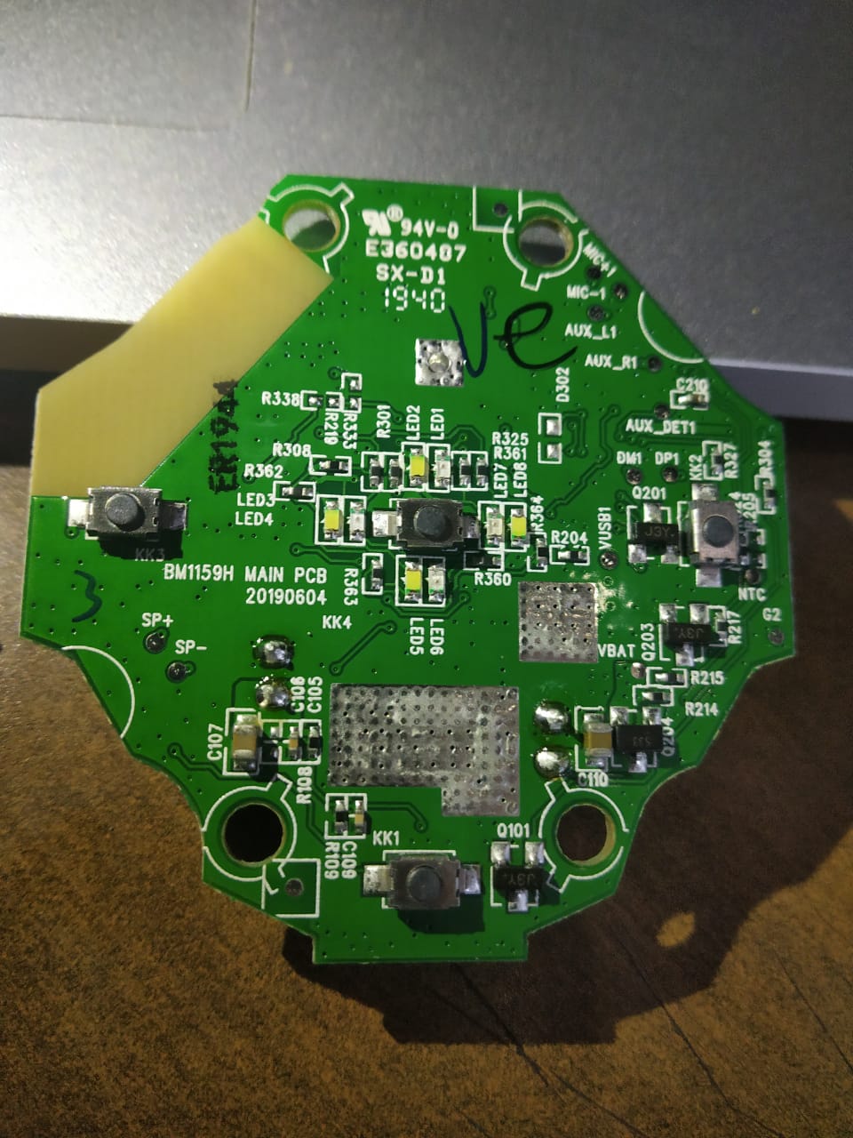
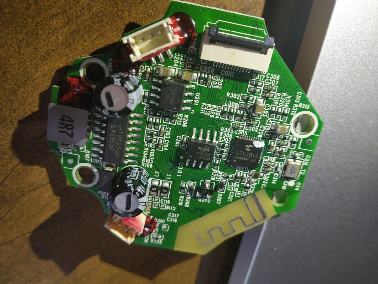
3 - Read online maybe I need to manually get at the firmware using something called JTAG, so I opened up the speaker and took out the board to inspect it. Here are its front and back:

enter image description here enter image description here

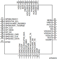
4 - I can't see an obvious JTAG interface. So I looked up the data sheet for the main chip : ATS2815, which seems to be a fully integrated blue tooth audio chip.

enter image description here

Even though I looked at its pin layout, I can't figure out if JTAG is present?

5 - I also looked up the chip XT25F08B, and that seems to be a NOR flash memory. Here is the data sheet.

What I'm wondering is:

  • Where is the JTAG interface? Am I missing something obvious?
  • My guess is that the firmware must reside on XT25F08B flash memory. Is this correct?
  • If it is true, then is there a simple and direct way to read/write this memory without bothering with JTAG (if it's not present or can't be figured out)?

Maybe all this is entirely the wrong approach, and there is another way to get at the firmware?
2
  • it looks like you have uart port on top left in the first figure. you can try to use this serial-in-out port to extract the firmware
    – R4444
    Commented Apr 22, 2021 at 14:54
  • Thats unfortunately not a uart port. I checked, the battery connects to it. And the other port symmetrically opposite it is the speaker output. Unless you were pointing to something else and I misunderstood..
    – Capstone
    Commented Apr 22, 2021 at 17:14

2 Answers 2

6

Based on a datasheet found on Internet (http://www.lanzhi-tech.com/filedownload/99240) it seems that the ATS2815 is a chip that has everything to manage a Bluetooth speaker and, probably, it is inside a lot of different speakers, all with the same interface.

According to the datasheet it has "internal ROM and internal RAM for program and data". So, I suppose, that the core firmware that implements the Bluetooth protocol and the main chip features is inside the ATS2815 chip.

On the external NOR flash EEPROM XT25F08B, which is 1Mbyte in size (8 Mbit), probably there is configuration data (like information on his Bluetooth name, paired devices, and so on) and maybe, but not sure on this, some "application" that can be loaded in RAM and executed.

On the Datasheet, there are multiple pins labeled UART_TX or UART_RX but it says also that the chip has only one UART interface; anyway I would try to see if on some of these pins there is something printed during the boot cycle.

You can also try to read the NOR flash using an 8 pin adapter like this one: https://amzn.to/39A9JFd, an EEPROM flash programmer like the "TL866II Plus" (or cheaper clones) and the related Xgpro EEPROM reader/programmer software.

According to the datasheet, it seems that the ATS1815 chip doesn't have a JTag interface, so it seems that this interface is not available here.

1
  • 1
    That clarifies a lot of things. Specially about JTAG not being present. So I don't waste time looking for it. I've ordered the SOIC clip and hopefully I'll be able to read the NOR memory when it arrives. I'm curious about the boot cycle you mentioned. How would I interface with the chip to get at that? Use another clip? Or use uart? But I don't know where the uart interface is either..
    – Capstone
    Commented Apr 23, 2021 at 19:47
4

You may be right that the firmware is stored on the xt25f08b chip. It's not uncommon for firmware to be stored on a flash chip like that, and I don't see any other storage.

One fairly simple way is to attach an 8-pin SOIC clip to the chip while the device is powered off, and read it over SPI. This can be done with a $5 Raspberry Pi and the open source flashrom software. If your chip isn't already supported there, it may be easy to add it if there is already a similar one. Sometimes you may run into issues if the connection causes the CPU to turn on, which could require removing a pin temporarily or pulling up/down some other pin.

Your Answer

By clicking “Post Your Answer”, you agree to our terms of service and acknowledge you have read our privacy policy.

Not the answer you're looking for? Browse other questions tagged or ask your own question.