5

I have recently been sifting my way through a whole load of assembly to try to identify how a program is decrypting some data. Thus far I have identified how the IV is extracted, that the IV is 16 bytes long and that the decryption method uses Cipher Block Chaining. Consequently I believe that the encryption method being used is AES-128-CBC.

The next step has been to try to identify the key being used to decrypt with, the issue is that the assembly for the individual block cipher encryption is about 2.5MB in size. However, what I have observed is that it is all of a very similar form, for example, a snippet:

add.w      r0, r12, #0x13
str.w      r0, [lr, #0x44]
tst.w      r0, #0xff
mov        r0, r12
it         eq
eoreq      r0, r12, #0x75

add.w      r1, r12, #0x5d
str.w      r1, [sp, #0xf00]
tst.w      r1, #0xff
it         eq
addeq      r0, #0x3b

r12 contains the encrypted data, loaded from a passed in argument (r0) as follows:

mov        r4, r0
add.w      lr, sp, #0x1000
ldrb.w     r12, [r4]

All of the assembly in the subroutine is of the exemplar form, some offset is added to the encrypted data, stored, tested against 0xff (always 0xff) and then some operation is performed as a result, either XOR, OR, ADD or MOV affecting another register (in the examples that is r0).

My current hunch is that this may be an AES-128 implementation with unrolled rounds.

Does this look AES-128 to you and do you agree the encryption been deliberately obfuscated to hide the key? If so then how has it been obfuscated and would it be possible to find the key?

Additional info

Here's a link to the full ASM file for the block cipher encryption subroutine.

And this is a link to the subroutine that uses CBC and calls the above subroutine referenced in the main question.

7
  • 1
    Based on the above snippets, it does not seems to be AES-128 to me, but could you share a larger snippet or the whole function?
    – ebux
    Commented Feb 9, 2016 at 12:21
  • @ebux This is the procedure I believe to be using CBC and this is an extended snippet of the block cipher function mentioned in the question (not full as it's a 60MB asm file). The arguments to the calls I believe are as follows sub_44d84(<decryptionFunction=0x1>, <IV>, <bytesToDecrypt>, <decryptedBytes>) and sub_46d554(<bytesToDecrypt>, <output>).
    – Joshua
    Commented Feb 9, 2016 at 13:39
  • Although it is hard to follow the code without the addresses, your CBC assumption may be correct. But in the cipher code I can see only that it read out the first byte of the input buffer and fill up a buffer with the modified values of the input byte. It would be interesting also how the output is generated (r3 stores the output pointer) and how the generated buffer is used later on the function.
    – ebux
    Commented Feb 10, 2016 at 8:02
  • @ebux I've updated those snippets with the addresses if it that helps somewhat. Would it be helpful if I uploaded the full ASM file so you can look at what the function looks like towards the end?
    – Joshua
    Commented Feb 10, 2016 at 18:06
  • The full ASM file would be fine.
    – ebux
    Commented Feb 11, 2016 at 7:01

1 Answer 1

3
+50

I think you identified the purpose of the functions and its parameters correctly. So, the function sub_44d84 has four parameters: (<decryptionFunction=0x1>, <IV>, <bytesToDecrypt>, <decryptedBytes>) and calls the sub_46d554 function for every blocks using CBC.

The sub_46d554 function received 2 parameters:

  • R0: Encrypted input block
  • R1: Decrypted output block

The bytes from the input blocks are read out from the first part of the function, performs the decryption steps and writes out to the output buffer in the last part of the function.

To understand the decryption function, first building blocks of the obfuscation should be understand. So, I picked up some example codes after the second bytes was read out from the input block (the start of the function is a little bit messy because of the compiler optimization).
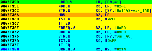
enter image description here

In the above image the line marked with green reads out the second byte of the input block and the orange line initializes the R2 register. The yellow and blue blocks are perform similar functions. Both blocks starts with an addition, stores the result to a local variable and check whether the result was equal to 0xFF. If the result was 0xFF the value of the R2 was changed. Since the R2 was changed only if the addition was 0xFF and the addition used always the LR (which contained the second byte of the input), the value of the R2 register can be changed only once. Because the new R2 value depends only from the LR these blocks implements a lookup table, which is a substitution box.

[EDIT] The lookup table is built up from the building blocks similar to the highlighted ones. So, in pseudo code, the lookup table is implemented in the following way:

if (input == 0xb1) out = 0x5b
if (input == 0x42) out = 0x56
...

To understand the reason why the result is stored into a local variable, let's check the next usage of the local variable var_1A8.

enter image description here

It reads out the local variable, which was the result of the addition, and checks whether it is 0xFF similar to the previous cases. Since the value of this local variable will be 0xFF only if the result of the addition was 0xFF in the place, where the value was originally stored, the comparison checks whether the input byte is equal to a specific value again.

If we search for the local variable var_1A8 in the whole function, we receive a lot of results with a specific patter (STR, LDR, LDR, LDR) repeatedly.

enter image description here

The STR means the storage of the addition and the LDR means the usage of this addition. So, every bytes are checked four times and than another byte will be used.

By comparing all of the input bytes usages with the local variable usages, the following patter can be found:

i0 = input[0x00]
d0_0 = table0[i0]
id = input[0x0d]
d0_d = table1[id]
ia = input[0x0a]
d0_a = table2[ia]
i7 = input[0x07]
d0_7 = table3[i7]

d1_0 = table4[i0]
d1_d = table5[id]
d1_a = table6[ia]
d1_7 = table7[i7]

d2_0 = table8[i0]
d2_d = table9[id]
d2_a = table10[ia]
d2_7 = table11[i7]

d3_0 = table12[i0]
d3_d = table13[id]
d3_a = table14[ia]
d3_7 = table15[i7]

So, reads out 4 bytes, performs the substitution and stores the result in a local variable. After it, the same was performed with the next 4 bytes and so on. After the whole block was processed the stored results were read out and xored value of some previous results was used as a new input, for example:

nb_0 = d0_4 ^ d2_d ^ ...
d0_0 = table16[nb_0]
nb_1 = d1_2 ^ d3_8 ^ ...
d0_1 = table17[nb_1]
...

d1_0 = table20[nb_0]
d1_d = table21[nb_1]
...

By checking the pattern of the local variable usage, it clearly seen that it uses 9 round of substitution.

Based on the above, I think, that the decryption function can be an AES-128 implementation. Because the add round key, sub bytes and shift rows steps operations can be implemented with lookup tables in one step, and the mix columns operation in another step. Because there is 9 round only, the initial round and the first round of the AES may be implemented with one lookup table.

So, the key (if it is really an AES implementation, the expanded key) is mixed into the implementation. Although I'm not a crytographer, I guess that you may retrieve the expanded AES key by xoring the values of the lookup tables with the Rijndael S-Box values. However, it seems to be a hard and time-consuming process, so you may consider to emulate the code if you want to just decrypt some data.

9
  • This is an excellent answer, thank you very much @ebux. From the sounds of things it looks like you've identified the intermediate 9 rounds of AES with the SubBytes step (the first pattern you found) and the MixColumns step (the second pattern, XORing with previous results) within each round. That makes me wonder then about the ShiftRows and AddRoundKey steps. During decryption the last round (10th) will simply add the original key using bitwise XOR, have you seen anything like this at the end of the function?
    – Joshua
    Commented Feb 15, 2016 at 12:27
  • The AES works with the expanded key and not the original key in each round. In the end of the last round, the result of the lookup is stored in the output buffer, which can mean an AddRoundKey step or a mix of some other steps also.
    – ebux
    Commented Feb 15, 2016 at 12:34
  • Indeed it works with the expanded key in all but the first round of encryption (last round of decryption) which is when it uses the original key as the first 16 bytes of the expanded key are simply the encryption key itself. I see, I will take another look myself.
    – Joshua
    Commented Feb 15, 2016 at 12:46
  • You are right, but the last ShiftRows and SubBytes steps can be combined with the last AddRoundKey step.
    – ebux
    Commented Feb 15, 2016 at 12:57
  • Ah I see — have you any thoughts on how it is performing the ShiftRows step? Also, may have missed it in your question but where are the lookup tables stored (i.e. ``table0`)?
    – Joshua
    Commented Feb 15, 2016 at 13:04

Your Answer

By clicking “Post Your Answer”, you agree to our terms of service and acknowledge you have read our privacy policy.

Not the answer you're looking for? Browse other questions tagged or ask your own question.